QuantumCircuit#
- class qiskit.circuit.QuantumCircuit(*regs, name=None, global_phase=0, metadata=None)[ソース]#
ベースクラス:
objectCreate a new circuit.
A circuit is a list of instructions bound to some registers.
- パラメータ:
regs (list(
Register) or list(int) or list(list(Bit))) –The registers to be included in the circuit.
If a list of
Registerobjects, represents theQuantumRegisterand/orClassicalRegisterobjects to include in the circuit.For example:
QuantumCircuit(QuantumRegister(4))QuantumCircuit(QuantumRegister(4), ClassicalRegister(3))QuantumCircuit(QuantumRegister(4, 'qr0'), QuantumRegister(2, 'qr1'))
If a list of
int, the amount of qubits and/or classical bits to include in the circuit. It can either be a single int for just the number of quantum bits, or 2 ints for the number of quantum bits and classical bits, respectively.For example:
QuantumCircuit(4) # A QuantumCircuit with 4 qubitsQuantumCircuit(4, 3) # A QuantumCircuit with 4 qubits and 3 classical bits
If a list of python lists containing
Bitobjects, a collection ofBits to be added to the circuit.
name (str) – the name of the quantum circuit. If not set, an automatically generated string will be assigned.
global_phase (float or ParameterExpression) – The global phase of the circuit in radians.
metadata (dict) – Arbitrary key value metadata to associate with the circuit. This gets stored as free-form data in a dict in the
metadataattribute. It will not be directly used in the circuit.
- 例外:
CircuitError – if the circuit name, if given, is not valid.
サンプル
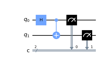
Construct a simple Bell state circuit.
from qiskit import QuantumCircuit

qc = QuantumCircuit(2, 2)
qc.h(0)
qc.cx(0, 1)
qc.measure([0, 1], [0, 1])
qc.draw('mpl')
Construct a 5-qubit GHZ circuit.
from qiskit import QuantumCircuit

qc = QuantumCircuit(5)
qc.h(0)
qc.cx(0, range(1, 5))
qc.measure_all()
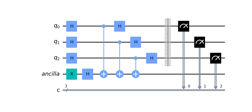
Construct a 4-qubit Bernstein-Vazirani circuit using registers.
from qiskit import QuantumRegister, ClassicalRegister, QuantumCircuit

qr = QuantumRegister(3, 'q')
anc = QuantumRegister(1, 'ancilla')
cr = ClassicalRegister(3, 'c')
qc = QuantumCircuit(qr, anc, cr)

qc.x(anc[0])
qc.h(anc[0])
qc.h(qr[0:3])
qc.cx(qr[0:3], anc[0])
qc.h(qr[0:3])
qc.barrier(qr)
qc.measure(qr, cr)

qc.draw('mpl')
Attributes
- ancillas#
Returns a list of ancilla bits in the order that the registers were added.
- calibrations#
Return calibration dictionary.
The custom pulse definition of a given gate is of the form
{'gate_name': {(qubits, params): schedule}}
- clbits#
Returns a list of classical bits in the order that the registers were added.
- data#
Return the circuit data (instructions and context).
- 戻り値:
a list-like object containing the
CircuitInstructions for each instruction.- 戻り値の型:
QuantumCircuitData
- extension_lib = 'include "qelib1.inc";'#
- global_phase#
Return the global phase of the circuit in radians.
- header = 'OPENQASM 2.0;'#
- instances = 153#
- layout#
Return any associated layout information about the circuit
This attribute contains an optional
TranspileLayoutobject. This is typically set on the output fromtranspile()orPassManager.run()to retain information about the permutations caused on the input circuit by transpilation.There are two types of permutations caused by the
transpile()function, an initial layout which permutes the qubits based on the selected physical qubits on theTarget, and a final layout which is an output permutation caused bySwapGates inserted during routing.
- metadata#
The user provided metadata associated with the circuit.
The metadata for the circuit is a user provided
dictof metadata for the circuit. It will not be used to influence the execution or operation of the circuit, but it is expected to be passed between all transforms of the circuit (ie transpilation) and that providers will associate any circuit metadata with the results it returns from execution of that circuit.
- num_ancillas#
Return the number of ancilla qubits.
- num_clbits#
Return number of classical bits.
- num_parameters#
The number of parameter objects in the circuit.
- num_qubits#
Return number of qubits.
- op_start_times#
Return a list of operation start times.
This attribute is enabled once one of scheduling analysis passes runs on the quantum circuit.
- 戻り値:
List of integers representing instruction start times. The index corresponds to the index of instruction in
QuantumCircuit.data.- 例外:
AttributeError – When circuit is not scheduled.
- parameters#
The parameters defined in the circuit.
This attribute returns the
Parameterobjects in the circuit sorted alphabetically. Note that parameters instantiated with aParameterVectorare still sorted numerically.サンプル
The snippet below shows that insertion order of parameters does not matter.
>>> from qiskit.circuit import QuantumCircuit, Parameter
>>> a, b, elephant = Parameter("a"), Parameter("b"), Parameter("elephant")
>>> circuit = QuantumCircuit(1)
>>> circuit.rx(b, 0)
>>> circuit.rz(elephant, 0)
>>> circuit.ry(a, 0)
>>> circuit.parameters  # sorted alphabetically!
ParameterView([Parameter(a), Parameter(b), Parameter(elephant)])
Bear in mind that alphabetical sorting might be unintuitive when it comes to numbers. The literal 「10」 comes before 「2」 in strict alphabetical sorting.
>>> from qiskit.circuit import QuantumCircuit, Parameter
>>> angles = [Parameter("angle_1"), Parameter("angle_2"), Parameter("angle_10")]
>>> circuit = QuantumCircuit(1)
>>> circuit.u(*angles, 0)
>>> circuit.draw()
   ┌─────────────────────────────┐
q: ┤ U(angle_1,angle_2,angle_10) ├
   └─────────────────────────────┘
>>> circuit.parameters
ParameterView([Parameter(angle_1), Parameter(angle_10), Parameter(angle_2)])
To respect numerical sorting, a
ParameterVectorcan be used.>>> from qiskit.circuit import QuantumCircuit, Parameter, ParameterVector >>> x = ParameterVector("x", 12) >>> circuit = QuantumCircuit(1) >>> for x_i in x: ... circuit.rx(x_i, 0) >>> circuit.parameters ParameterView([ ParameterVectorElement(x[0]), ParameterVectorElement(x[1]), ParameterVectorElement(x[2]), ParameterVectorElement(x[3]), ..., ParameterVectorElement(x[11]) ])
- 戻り値:
The sorted
Parameterobjects in the circuit.
- prefix = 'circuit'#
- qubits#
Returns a list of quantum bits in the order that the registers were added.
Methods
- add_calibration(gate, qubits, schedule, params=None)[ソース]#
Register a low-level, custom pulse definition for the given gate.
- append(instruction, qargs=None, cargs=None)[ソース]#
Append one or more instructions to the end of the circuit, modifying the circuit in place.
The
qargsandcargswill be expanded and broadcast according to the rules of the givenInstruction, and any non-Bitspecifiers (such as integer indices) will be resolved into the relevant instances.If a
CircuitInstructionis given, it will be unwrapped, verified in the context of this circuit, and a new object will be appended to the circuit. In this case, you may not passqargsorcargsseparately.- パラメータ:
instruction (Operation | CircuitInstruction) –
Instructioninstance to append, or aCircuitInstructionwith all its context.qargs (Sequence[QubitSpecifier] | None) – specifiers of the
Qubits to attach instruction to.cargs (Sequence[ClbitSpecifier] | None) – specifiers of the
Clbits to attach instruction to.
- 戻り値:
a handle to the
CircuitInstructions that were actually added to the circuit.- 戻り値の型:
- 例外:
CircuitError – if the operation passed is not an instance of
Instruction.
- assign_parameters(parameters: Mapping[Parameter, ParameterExpression | float] | Sequence[ParameterExpression | float], inplace: Literal[False] = False, *, flat_input: bool = False, strict: bool = True) QuantumCircuit[ソース]#
- assign_parameters(parameters: Mapping[Parameter, ParameterExpression | float] | Sequence[ParameterExpression | float], inplace: Literal[True] = False, *, flat_input: bool = False, strict: bool = True) None
Assign parameters to new parameters or values.
If
parametersis passed as a dictionary, the keys must beParameterinstances in the current circuit. The values of the dictionary can either be numeric values or new parameter objects.If
parametersis passed as a list or array, the elements are assigned to the current parameters in the order ofparameterswhich is sorted alphabetically (while respecting the ordering inParameterVectorobjects).The values can be assigned to the current circuit object or to a copy of it.
- パラメータ:
parameters – Either a dictionary or iterable specifying the new parameter values.
inplace – If False, a copy of the circuit with the bound parameters is returned. If True the circuit instance itself is modified.
flat_input – If
Trueandparametersis a mapping type, it is assumed to be exactly a mapping of{parameter: value}. By default (False), the mapping may also containParameterVectorkeys that point to a corresponding sequence of values, and these will be unrolled during the mapping.strict – If
False, any parameters given in the mapping that are not used in the circuit will be ignored. IfTrue(the default), an error will be raised indicating a logic error.
- 例外:
CircuitError – If parameters is a dict and contains parameters not present in the circuit.
ValueError – If parameters is a list/array and the length mismatches the number of free parameters in the circuit.
- 戻り値:
A copy of the circuit with bound parameters if
inplaceis False, otherwise None.
サンプル
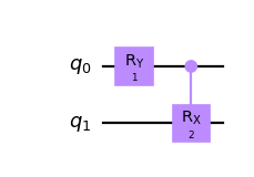
Create a parameterized circuit and assign the parameters in-place.
from qiskit.circuit import QuantumCircuit, Parameter

circuit = QuantumCircuit(2)
params = [Parameter('A'), Parameter('B'), Parameter('C')]
circuit.ry(params[0], 0)
circuit.crx(params[1], 0, 1)
circuit.draw('mpl')
circuit.assign_parameters({params[0]: params[2]}, inplace=True)
circuit.draw('mpl')


Bind the values out-of-place by list and get a copy of the original circuit.
from qiskit.circuit import QuantumCircuit, ParameterVector

circuit = QuantumCircuit(2)
params = ParameterVector('P', 2)
circuit.ry(params[0], 0)
circuit.crx(params[1], 0, 1)

bound_circuit = circuit.assign_parameters([1, 2])
bound_circuit.draw('mpl')

circuit.draw('mpl')

- barrier(*qargs, label=None)[ソース]#
Apply
Barrier. Ifqargsis empty, applies to all qubits in the circuit.- パラメータ:
qargs (QubitSpecifier) – Specification for one or more qubit arguments.
label (str) – The string label of the barrier.
- 戻り値:
handle to the added instructions.
- 戻り値の型:
- bind_parameters(values)[ソース]#
Assign numeric parameters to values yielding a new circuit.
If the values are given as list or array they are bound to the circuit in the order of
parameters(see the docstring for more details).To assign new Parameter objects or bind the values in-place, without yielding a new circuit, use the
assign_parameters()method.- パラメータ:
values (Mapping[Parameter, float] | Sequence[float]) –
{parameter: value, ...}or[value1, value2, ...]- 例外:
CircuitError – If values is a dict and contains parameters not present in the circuit.
TypeError – If values contains a ParameterExpression.
- 戻り値:
Copy of self with assignment substitution.
- 戻り値の型:
- break_loop()[ソース]#
Apply
BreakLoopOp.警告
If you are using the context-manager 「builder」 forms of
if_test(),for_loop()orwhile_loop(), you can only call this method if you are within a loop context, because otherwise the 「resource width」 of the operation cannot be determined. This would quickly lead to invalid circuits, and so if you are trying to construct a reusable loop body (without the context managers), you must also use the non-context-manager form ofif_test()andif_else(). Take care that theBreakLoopOpinstruction must span all the resources of its containing loop, not just the immediate scope.- 戻り値:
A handle to the instruction created.
- 例外:
CircuitError – if this method was called within a builder context, but not contained within a loop.
- 戻り値の型:
- static cast(value, type_)[ソース]#
Best effort to cast value to type. Otherwise, returns the value.
- 戻り値の型:
S | T
- cbit_argument_conversion(clbit_representation)[ソース]#
Converts several classical bit representations (such as indexes, range, etc.) into a list of classical bits.
- パラメータ:
clbit_representation (Object) – representation to expand
- 戻り値:
Where each tuple is a classical bit.
- 戻り値の型:
List(tuple)
- ccx(control_qubit1, control_qubit2, target_qubit, ctrl_state=None)[ソース]#
Apply
CCXGate.For the full matrix form of this gate, see the underlying gate documentation.
- パラメータ:
control_qubit1 (QubitSpecifier) – The qubit(s) used as the first control.
control_qubit2 (QubitSpecifier) – The qubit(s) used as the second control.
target_qubit (QubitSpecifier) – The qubit(s) targeted by the gate.
ctrl_state (str | int | None) – The control state in decimal, or as a bitstring (e.g. 『1』). Defaults to controlling on the 『1』 state.
- 戻り値:
A handle to the instructions created.
- 戻り値の型:
- ccz(control_qubit1, control_qubit2, target_qubit, label=None, ctrl_state=None)[ソース]#
Apply
CCZGate.For the full matrix form of this gate, see the underlying gate documentation.
- パラメータ:
control_qubit1 (QubitSpecifier) – The qubit(s) used as the first control.
control_qubit2 (QubitSpecifier) – The qubit(s) used as the second control.
target_qubit (QubitSpecifier) – The qubit(s) targeted by the gate.
label (str | None) – The string label of the gate in the circuit.
ctrl_state (str | int | None) – The control state in decimal, or as a bitstring (e.g. 『10』). Defaults to controlling on the 『11』 state.
- 戻り値:
A handle to the instructions created.
- 戻り値の型:
- ch(control_qubit, target_qubit, label=None, ctrl_state=None)[ソース]#
Apply
CHGate.For the full matrix form of this gate, see the underlying gate documentation.
- パラメータ:
control_qubit (QubitSpecifier) – The qubit(s) used as the control.
target_qubit (QubitSpecifier) – The qubit(s) targeted by the gate.
label (str | None) – The string label of the gate in the circuit.
ctrl_state (str | int | None) – The control state in decimal, or as a bitstring (e.g. 『1』). Defaults to controlling on the 『1』 state.
- 戻り値:
A handle to the instructions created.
- 戻り値の型:
- clear()[ソース]#
Clear all instructions in self.
Clearing the circuits will keep the metadata and calibrations.
- classmethod cls_instances()[ソース]#
Return the current number of instances of this class, useful for auto naming.
- 戻り値の型:
- cnot(control_qubit, target_qubit, label=None, ctrl_state=None)[ソース]#
Apply
CXGate.For the full matrix form of this gate, see the underlying gate documentation.
- パラメータ:
control_qubit (QubitSpecifier) – The qubit(s) used as the control.
target_qubit (QubitSpecifier) – The qubit(s) targeted by the gate.
label (str | None) – The string label of the gate in the circuit.
ctrl_state (str | int | None) – The control state in decimal, or as a bitstring (e.g. 『1』). Defaults to controlling on the 『1』 state.
- 戻り値:
A handle to the instructions created.
- 戻り値の型:
参考
QuantumCircuit.cx: the same function with a different name.
- compose(other, qubits=None, clbits=None, front=False, inplace=False, wrap=False)[ソース]#
Compose circuit with
othercircuit or instruction, optionally permuting wires.othercan be narrower or of equal width toself.- パラメータ:
other (qiskit.circuit.Instruction or QuantumCircuit) – (sub)circuit or instruction to compose onto self. If not a
QuantumCircuit, this can be anything thatappendwill accept.front (bool) – If True, front composition will be performed. This is not possible within control-flow builder context managers.
inplace (bool) – If True, modify the object. Otherwise return composed circuit.
wrap (bool) – If True, wraps the other circuit into a gate (or instruction, depending on whether it contains only unitary instructions) before composing it onto self.
- 戻り値:
the composed circuit (returns None if inplace==True).
- 戻り値の型:
- 例外:
CircuitError – if no correct wire mapping can be made between the two circuits, such as if
otheris wider thanself.CircuitError – if trying to emit a new circuit while
selfhas a partially built control-flow context active, such as the context-manager forms ofif_test(),for_loop()andwhile_loop().CircuitError – if trying to compose to the front of a circuit when a control-flow builder block is active; there is no clear meaning to this action.
サンプル
>>> lhs.compose(rhs, qubits=[3, 2], inplace=True)
            ┌───┐                   ┌─────┐                ┌───┐
lqr_1_0: ───┤ H ├───    rqr_0: ──■──┤ Tdg ├    lqr_1_0: ───┤ H ├───────────────
            ├───┤              ┌─┴─┐└─────┘                ├───┤
lqr_1_1: ───┤ X ├───    rqr_1: ┤ X ├───────    lqr_1_1: ───┤ X ├───────────────
         ┌──┴───┴──┐           └───┘                    ┌──┴───┴──┐┌───┐
lqr_1_2: ┤ U1(0.1) ├  +                     =  lqr_1_2: ┤ U1(0.1) ├┤ X ├───────
         └─────────┘                                    └─────────┘└─┬─┘┌─────┐
lqr_2_0: ─────■─────                           lqr_2_0: ─────■───────■──┤ Tdg ├
            ┌─┴─┐                                          ┌─┴─┐        └─────┘
lqr_2_1: ───┤ X ├───                           lqr_2_1: ───┤ X ├───────────────
            └───┘                                          └───┘
lcr_0: 0 ═══════════                           lcr_0: 0 ═══════════════════════

lcr_1: 0 ═══════════                           lcr_1: 0 ═══════════════════════
- continue_loop()[ソース]#
Apply
ContinueLoopOp.警告
If you are using the context-manager 「builder」 forms of
if_test(),for_loop()orwhile_loop(), you can only call this method if you are within a loop context, because otherwise the 「resource width」 of the operation cannot be determined. This would quickly lead to invalid circuits, and so if you are trying to construct a reusable loop body (without the context managers), you must also use the non-context-manager form ofif_test()andif_else(). Take care that theContinueLoopOpinstruction must span all the resources of its containing loop, not just the immediate scope.- 戻り値:
A handle to the instruction created.
- 例外:
CircuitError – if this method was called within a builder context, but not contained within a loop.
- 戻り値の型:
- control(num_ctrl_qubits=1, label=None, ctrl_state=None)[ソース]#
Control this circuit on
num_ctrl_qubitsqubits.- パラメータ:
- 戻り値:
The controlled version of this circuit.
- 戻り値の型:
- 例外:
CircuitError – If the circuit contains a non-unitary operation and cannot be controlled.
- copy(name=None)[ソース]#
Copy the circuit.
- パラメータ:
name (str) – name to be given to the copied circuit. If None, then the name stays the same
- 戻り値:
a deepcopy of the current circuit, with the specified name
- 戻り値の型:
- copy_empty_like(name=None)[ソース]#
Return a copy of self with the same structure but empty.
- That structure includes:
name, calibrations and other metadata
global phase
all the qubits and clbits, including the registers
- パラメータ:
name (str) – Name for the copied circuit. If None, then the name stays the same.
- 戻り値:
An empty copy of self.
- 戻り値の型:
- count_ops()[ソース]#
Count each operation kind in the circuit.
- 戻り値:
a breakdown of how many operations of each kind, sorted by amount.
- 戻り値の型:
OrderedDict
- cp(theta, control_qubit, target_qubit, label=None, ctrl_state=None)[ソース]#
Apply
CPhaseGate.For the full matrix form of this gate, see the underlying gate documentation.
- パラメータ:
theta (ParameterValueType) – The angle of the rotation.
control_qubit (QubitSpecifier) – The qubit(s) used as the control.
target_qubit (QubitSpecifier) – The qubit(s) targeted by the gate.
label (str | None) – The string label of the gate in the circuit.
ctrl_state (str | int | None) – The control state in decimal, or as a bitstring (e.g. 『1』). Defaults to controlling on the 『1』 state.
- 戻り値:
A handle to the instructions created.
- 戻り値の型:
- crx(theta, control_qubit, target_qubit, label=None, ctrl_state=None)[ソース]#
Apply
CRXGate.For the full matrix form of this gate, see the underlying gate documentation.
- パラメータ:
theta (ParameterValueType) – The angle of the rotation.
control_qubit (QubitSpecifier) – The qubit(s) used as the control.
target_qubit (QubitSpecifier) – The qubit(s) targeted by the gate.
label (str | None) – The string label of the gate in the circuit.
ctrl_state (str | int | None) – The control state in decimal, or as a bitstring (e.g. 『1』). Defaults to controlling on the 『1』 state.
- 戻り値:
A handle to the instructions created.
- 戻り値の型:
- cry(theta, control_qubit, target_qubit, label=None, ctrl_state=None)[ソース]#
Apply
CRYGate.For the full matrix form of this gate, see the underlying gate documentation.
- パラメータ:
theta (ParameterValueType) – The angle of the rotation.
control_qubit (QubitSpecifier) – The qubit(s) used as the control.
target_qubit (QubitSpecifier) – The qubit(s) targeted by the gate.
label (str | None) – The string label of the gate in the circuit.
ctrl_state (str | int | None) – The control state in decimal, or as a bitstring (e.g. 『1』). Defaults to controlling on the 『1』 state.
- 戻り値:
A handle to the instructions created.
- 戻り値の型:
- crz(theta, control_qubit, target_qubit, label=None, ctrl_state=None)[ソース]#
Apply
CRZGate.For the full matrix form of this gate, see the underlying gate documentation.
- パラメータ:
theta (ParameterValueType) – The angle of the rotation.
control_qubit (QubitSpecifier) – The qubit(s) used as the control.
target_qubit (QubitSpecifier) – The qubit(s) targeted by the gate.
label (str | None) – The string label of the gate in the circuit.
ctrl_state (str | int | None) – The control state in decimal, or as a bitstring (e.g. 『1』). Defaults to controlling on the 『1』 state.
- 戻り値:
A handle to the instructions created.
- 戻り値の型:
- cs(control_qubit, target_qubit, label=None, ctrl_state=None)[ソース]#
Apply
CSGate.For the full matrix form of this gate, see the underlying gate documentation.
- パラメータ:
control_qubit (QubitSpecifier) – The qubit(s) used as the control.
target_qubit (QubitSpecifier) – The qubit(s) targeted by the gate.
label (str | None) – The string label of the gate in the circuit.
ctrl_state (str | int | None) – The control state in decimal, or as a bitstring (e.g. 『1』). Defaults to controlling on the 『1』 state.
- 戻り値:
A handle to the instructions created.
- 戻り値の型:
- csdg(control_qubit, target_qubit, label=None, ctrl_state=None)[ソース]#
Apply
CSdgGate.For the full matrix form of this gate, see the underlying gate documentation.
- パラメータ:
control_qubit (QubitSpecifier) – The qubit(s) used as the control.
target_qubit (QubitSpecifier) – The qubit(s) targeted by the gate.
label (str | None) – The string label of the gate in the circuit.
ctrl_state (str | int | None) – The control state in decimal, or as a bitstring (e.g. 『1』). Defaults to controlling on the 『1』 state.
- 戻り値:
A handle to the instructions created.
- 戻り値の型:
- cswap(control_qubit, target_qubit1, target_qubit2, label=None, ctrl_state=None)[ソース]#
Apply
CSwapGate.For the full matrix form of this gate, see the underlying gate documentation.
- パラメータ:
control_qubit (QubitSpecifier) – The qubit(s) used as the control.
target_qubit1 (QubitSpecifier) – The qubit(s) targeted by the gate.
target_qubit2 (QubitSpecifier) – The qubit(s) targeted by the gate.
label (str | None) – The string label of the gate in the circuit.
ctrl_state (str | int | None) – The control state in decimal, or as a bitstring (e.g.
'1'). Defaults to controlling on the'1'state.
- 戻り値:
A handle to the instructions created.
- 戻り値の型:
- csx(control_qubit, target_qubit, label=None, ctrl_state=None)[ソース]#
Apply
CSXGate.For the full matrix form of this gate, see the underlying gate documentation.
- パラメータ:
control_qubit (QubitSpecifier) – The qubit(s) used as the control.
target_qubit (QubitSpecifier) – The qubit(s) targeted by the gate.
label (str | None) – The string label of the gate in the circuit.
ctrl_state (str | int | None) – The control state in decimal, or as a bitstring (e.g. 『1』). Defaults to controlling on the 『1』 state.
- 戻り値:
A handle to the instructions created.
- 戻り値の型:
- cu(theta, phi, lam, gamma, control_qubit, target_qubit, label=None, ctrl_state=None)[ソース]#
Apply
CUGate.For the full matrix form of this gate, see the underlying gate documentation.
- パラメータ:
theta (ParameterValueType) – The \(\theta\) rotation angle of the gate.
phi (ParameterValueType) – The \(\phi\) rotation angle of the gate.
lam (ParameterValueType) – The \(\lambda\) rotation angle of the gate.
gamma (ParameterValueType) – The global phase applied of the U gate, if applied.
control_qubit (QubitSpecifier) – The qubit(s) used as the control.
target_qubit (QubitSpecifier) – The qubit(s) targeted by the gate.
label (str | None) – The string label of the gate in the circuit.
ctrl_state (str | int | None) – The control state in decimal, or as a bitstring (e.g. 『1』). Defaults to controlling on the 『1』 state.
- 戻り値:
A handle to the instructions created.
- 戻り値の型:
- cx(control_qubit, target_qubit, label=None, ctrl_state=None)[ソース]#
Apply
CXGate.For the full matrix form of this gate, see the underlying gate documentation.
- パラメータ:
control_qubit (QubitSpecifier) – The qubit(s) used as the control.
target_qubit (QubitSpecifier) – The qubit(s) targeted by the gate.
label (str | None) – The string label of the gate in the circuit.
ctrl_state (str | int | None) – The control state in decimal, or as a bitstring (e.g. 『1』). Defaults to controlling on the 『1』 state.
- 戻り値:
A handle to the instructions created.
- 戻り値の型:
- cy(control_qubit, target_qubit, label=None, ctrl_state=None)[ソース]#
Apply
CYGate.For the full matrix form of this gate, see the underlying gate documentation.
- パラメータ:
control_qubit (QubitSpecifier) – The qubit(s) used as the controls.
target_qubit (QubitSpecifier) – The qubit(s) targeted by the gate.
label (str | None) – The string label of the gate in the circuit.
ctrl_state (str | int | None) – The control state in decimal, or as a bitstring (e.g. 『1』). Defaults to controlling on the 『1』 state.
- 戻り値:
A handle to the instructions created.
- 戻り値の型:
- cz(control_qubit, target_qubit, label=None, ctrl_state=None)[ソース]#
Apply
CZGate.For the full matrix form of this gate, see the underlying gate documentation.
- パラメータ:
control_qubit (QubitSpecifier) – The qubit(s) used as the controls.
target_qubit (QubitSpecifier) – The qubit(s) targeted by the gate.
label (str | None) – The string label of the gate in the circuit.
ctrl_state (str | int | None) – The control state in decimal, or as a bitstring (e.g. 『1』). Defaults to controlling on the 『1』 state.
- 戻り値:
A handle to the instructions created.
- 戻り値の型:
- dcx(qubit1, qubit2)[ソース]#
Apply
DCXGate.For the full matrix form of this gate, see the underlying gate documentation.
- パラメータ:
- 戻り値:
A handle to the instructions created.
- 戻り値の型:
- decompose(gates_to_decompose=None, reps=1)[ソース]#
Call a decomposition pass on this circuit, to decompose one level (shallow decompose).
- パラメータ:
gates_to_decompose (type or str or list(type, str)) – Optional subset of gates to decompose. Can be a gate type, such as
HGate, or a gate name, such as 『h』, or a gate label, such as 『My H Gate』, or a list of any combination of these. If a gate name is entered, it will decompose all gates with that name, whether the gates have labels or not. Defaults to all gates in circuit.reps (int) – Optional number of times the circuit should be decomposed. For instance,
reps=2equals callingcircuit.decompose().decompose(). can decompose specific gates specific time
- 戻り値:
a circuit one level decomposed
- 戻り値の型:
- delay(duration, qarg=None, unit='dt')[ソース]#
Apply
Delay. If qarg isNone, applies to all qubits. When applying to multiple qubits, delays with the same duration will be created.- パラメータ:
duration (int or float or ParameterExpression) – duration of the delay.
qarg (Object) – qubit argument to apply this delay.
unit (str) – unit of the duration. Supported units:
's','ms','us','ns','ps', and'dt'. Default is'dt', i.e. integer time unit depending on the target backend.
- 戻り値:
handle to the added instructions.
- 戻り値の型:
- 例外:
CircuitError – if arguments have bad format.
- depth(filter_function=<function QuantumCircuit.<lambda>>)[ソース]#
Return circuit depth (i.e., length of critical path).
- パラメータ:
filter_function (callable) – A function to filter instructions. Should take as input a tuple of (Instruction, list(Qubit), list(Clbit)). Instructions for which the function returns False are ignored in the computation of the circuit depth. By default filters out 「directives」, such as barrier or snapshot.
- 戻り値:
Depth of circuit.
- 戻り値の型:
メモ
The circuit depth and the DAG depth need not be the same.
- diagonal(diag, qubit)#
Attach a diagonal gate to a circuit.
The decomposition is based on Theorem 7 given in 「Synthesis of Quantum Logic Circuits」 by Shende et al. (https://arxiv.org/pdf/quant-ph/0406176.pdf).
- パラメータ:
diag (list) – list of the 2^k diagonal entries (for a diagonal gate on k qubits). Must contain at least two entries
qubit (QuantumRegister|list) – list of k qubits the diagonal is acting on (the order of the qubits specifies the computational basis in which the diagonal gate is provided: the first element in diag acts on the state where all the qubits in q are in the state 0, the second entry acts on the state where all the qubits q[1],…,q[k-1] are in the state zero and q[0] is in the state 1, and so on)
- 戻り値:
the diagonal gate which was attached to the circuit.
- 戻り値の型:
- 例外:
QiskitError – if the list of the diagonal entries or the qubit list is in bad format; if the number of diagonal entries is not 2^k, where k denotes the number of qubits
- draw(output=None, scale=None, filename=None, style=None, interactive=False, plot_barriers=True, reverse_bits=None, justify=None, vertical_compression='medium', idle_wires=True, with_layout=True, fold=None, ax=None, initial_state=False, cregbundle=None, wire_order=None)[ソース]#
Draw the quantum circuit. Use the output parameter to choose the drawing format:
text: ASCII art TextDrawing that can be printed in the console.
mpl: images with color rendered purely in Python using matplotlib.
latex: high-quality images compiled via latex.
latex_source: raw uncompiled latex output.
警告
Support for
Exprnodes in conditions andSwitchCaseOp.targetfields is preliminary and incomplete. Thetextandmpldrawers will make a best-effort attempt to show data dependencies, but the LaTeX-based drawers will skip these completely.- パラメータ:
output (str) – select the output method to use for drawing the circuit. Valid choices are
text,mpl,latex,latex_source. By default the text drawer is used unless the user config file (usually~/.qiskit/settings.conf) has an alternative backend set as the default. For example,circuit_drawer = latex. If the output kwarg is set, that backend will always be used over the default in the user config file.scale (float) – scale of image to draw (shrink if < 1.0). Only used by the mpl, latex and latex_source outputs. Defaults to 1.0.
filename (str) – file path to save image to. Defaults to None.
style (dict or str) – dictionary of style or file name of style json file. This option is only used by the mpl or latex output type. If style is a str, it is used as the path to a json file which contains a style dict. The file will be opened, parsed, and then any style elements in the dict will replace the default values in the input dict. A file to be loaded must end in
.json, but the name entered here can omit.json. For example,style='iqx.json'orstyle='iqx'. If style is a dict and the'name'key is set, that name will be used to load a json file, followed by loading the other items in the style dict. For example,style={'name': 'iqx'}. If style is not a str and name is not a key in the style dict, then the default value from the user config file (usually~/.qiskit/settings.conf) will be used, for example,circuit_mpl_style = iqx. If none of these are set, the default style will be used. The search path for style json files can be specified in the user config, for example,circuit_mpl_style_path = /home/user/styles:/home/user. See:DefaultStylefor more information on the contents.interactive (bool) – when set to true, show the circuit in a new window (for mpl this depends on the matplotlib backend being used supporting this). Note when used with either the text or the latex_source output type this has no effect and will be silently ignored. Defaults to False.
reverse_bits (bool) – when set to True, reverse the bit order inside registers for the output visualization. Defaults to False unless the user config file (usually
~/.qiskit/settings.conf) has an alternative value set. For example,circuit_reverse_bits = True.plot_barriers (bool) – enable/disable drawing barriers in the output circuit. Defaults to True.
justify (string) – options are
left,rightornone. If anything else is supplied, it defaults to left justified. It refers to where gates should be placed in the output circuit if there is an option.noneresults in each gate being placed in its own column.vertical_compression (string) –
high,mediumorlow. It merges the lines generated by the text output so the drawing will take less vertical room. Default ismedium. Only used by the text output, will be silently ignored otherwise.idle_wires (bool) – include idle wires (wires with no circuit elements) in output visualization. Default is True.
with_layout (bool) – include layout information, with labels on the physical layout. Default is True.
fold (int) – sets pagination. It can be disabled using -1. In text, sets the length of the lines. This is useful when the drawing does not fit in the console. If None (default), it will try to guess the console width using
shutil.get_terminal_size(). However, if running in jupyter, the default line length is set to 80 characters. In mpl, it is the number of (visual) layers before folding. Default is 25.ax (matplotlib.axes.Axes) – Only used by the mpl backend. An optional Axes object to be used for the visualization output. If none is specified, a new matplotlib Figure will be created and used. Additionally, if specified there will be no returned Figure since it is redundant.
initial_state (bool) – Optional. Adds
|0>in the beginning of the wire. Default is False.cregbundle (bool) – Optional. If set True, bundle classical registers. Default is True, except for when
outputis set to"text".wire_order (list) – Optional. A list of integers used to reorder the display of the bits. The list must have an entry for every bit with the bits in the range 0 to (
num_qubits+num_clbits).
- 戻り値:
TextDrawingormatplotlib.figureorPIL.Imageorstr:- TextDrawing (output=』text』)
A drawing that can be printed as ascii art.
- matplotlib.figure.Figure (output=』mpl』)
A matplotlib figure object for the circuit diagram.
- PIL.Image (output=』latex』)
An in-memory representation of the image of the circuit diagram.
- str (output=』latex_source』)
The LaTeX source code for visualizing the circuit diagram.
- 例外:
VisualizationError – when an invalid output method is selected
ImportError – when the output methods requires non-installed libraries.
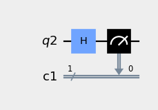
サンプル
from qiskit import QuantumRegister, ClassicalRegister, QuantumCircuit
q = QuantumRegister(1)
c = ClassicalRegister(1)
qc = QuantumCircuit(q, c)
qc.h(q)
qc.measure(q, c)
qc.draw(output='mpl', style={'backgroundcolor': '#EEEEEE'})
- ecr(qubit1, qubit2)[ソース]#
Apply
ECRGate.For the full matrix form of this gate, see the underlying gate documentation.
- パラメータ:
- 戻り値:
A handle to the instructions created.
- 戻り値の型:
- find_bit(bit)[ソース]#
Find locations in the circuit which can be used to reference a given
Bit.- パラメータ:
bit (Bit) – The bit to locate.
- 戻り値:
- A 2-tuple. The first element (
index) contains the index at which the
Bitcan be found (in eitherqubits,clbits, depending on its type). The second element (registers) is a list of(register, index)pairs with an entry for eachRegisterin the circuit which contains theBit(and the index in theRegisterat which it can be found).
- A 2-tuple. The first element (
- 戻り値の型:
メモ
The circuit index of an
AncillaQubitwill be its index inqubits, notancillas.- 例外:
CircuitError – If the supplied
Bitwas of an unknown type.CircuitError – If the supplied
Bitcould not be found on the circuit.
- 戻り値の型:
BitLocations
- for_loop(indexset: Iterable[int], loop_parameter: Parameter | None, body: None, qubits: None, clbits: None, *, label: str | None) qiskit.circuit.controlflow.for_loop.ForLoopContext[ソース]#
- for_loop(indexset: Iterable[int], loop_parameter: Parameter | None, body: QuantumCircuit, qubits: Sequence[Qubit | QuantumRegister | int | slice | Sequence[Qubit | int]], clbits: Sequence[Clbit | ClassicalRegister | int | slice | Sequence[Clbit | int]], *, label: str | None) InstructionSet
Create a
forloop on this circuit.There are two forms for calling this function. If called with all its arguments (with the possible exception of
label), it will create aForLoopOpwith the givenbody. Ifbody(andqubitsandclbits) are not passed, then this acts as a context manager, which, when entered, provides a loop variable (unless one is given, in which case it will be reused) and will automatically build aForLoopOpwhen the scope finishes. In this form, you do not need to keep track of the qubits or clbits you are using, because the scope will handle it for you.For example:
from qiskit import QuantumCircuit
qc = QuantumCircuit(2, 1)

with qc.for_loop(range(5)) as i:
    qc.h(0)
    qc.cx(0, 1)
    qc.measure(0, 0)
    qc.break_loop().c_if(0, True)
- パラメータ:
indexset (Iterable[int]) – A collection of integers to loop over. Always necessary.
loop_parameter (Optional[Parameter]) –
The parameter used within
bodyto which the values fromindexsetwill be assigned. In the context-manager form, if this argument is not supplied, then a loop parameter will be allocated for you and returned as the value of thewithstatement. This will only be bound into the circuit if it is used within the body.If this argument is
Nonein the manual form of this method,bodywill be repeated once for each of the items inindexsetbut their values will be ignored.body (Optional[QuantumCircuit]) – The loop body to be repeatedly executed. Omit this to use the context-manager mode.
qubits (Optional[Sequence[QubitSpecifier]]) – The circuit qubits over which the loop body should be run. Omit this to use the context-manager mode.
clbits (Optional[Sequence[ClbitSpecifier]]) – The circuit clbits over which the loop body should be run. Omit this to use the context-manager mode.
label (Optional[str]) – The string label of the instruction in the circuit.
- 戻り値:
depending on the call signature, either a context manager for creating the for loop (it will automatically be added to the circuit at the end of the block), or an
InstructionSethandle to the appended loop operation.- 戻り値の型:
InstructionSet or ForLoopContext
- 例外:
CircuitError – if an incorrect calling convention is used.
- fredkin(control_qubit, target_qubit1, target_qubit2)[ソース]#
Apply
CSwapGate.For the full matrix form of this gate, see the underlying gate documentation.
- パラメータ:
control_qubit (Qubit | QuantumRegister | int | slice | Sequence[Qubit | int]) – The qubit(s) used as the control.
target_qubit1 (Qubit | QuantumRegister | int | slice | Sequence[Qubit | int]) – The qubit(s) targeted by the gate.
target_qubit2 (Qubit | QuantumRegister | int | slice | Sequence[Qubit | int]) – The qubit(s) targeted by the gate.
- 戻り値:
A handle to the instructions created.
- 戻り値の型:
参考
QuantumCircuit.cswap: the same function with a different name.
- static from_instructions(instructions, *, qubits=(), clbits=(), name=None, global_phase=0, metadata=None)[ソース]#
Construct a circuit from an iterable of CircuitInstructions.
- パラメータ:
instructions (Iterable[CircuitInstruction | tuple[qiskit.circuit.Instruction] | tuple[qiskit.circuit.Instruction, Iterable[Qubit]] | tuple[qiskit.circuit.Instruction, Iterable[Qubit], Iterable[Clbit]]]) – The instructions to add to the circuit.
qubits (Iterable[Qubit]) – Any qubits to add to the circuit. This argument can be used, for example, to enforce a particular ordering of qubits.
clbits (Iterable[Clbit]) – Any classical bits to add to the circuit. This argument can be used, for example, to enforce a particular ordering of classical bits.
name (str | None) – The name of the circuit.
global_phase (ParameterValueType) – The global phase of the circuit in radians.
metadata (dict | None) – Arbitrary key value metadata to associate with the circuit.
- 戻り値:
The quantum circuit.
- 戻り値の型:
- static from_qasm_file(path)[ソース]#
Read an OpenQASM 2.0 program from a file and convert to an instance of
QuantumCircuit.- パラメータ:
path (str) – Path to the file for an OpenQASM 2 program
- 戻り値:
The QuantumCircuit object for the input OpenQASM 2.
- 戻り値の型:
参考
qasm2.load(): the complete interface to the OpenQASM 2 importer.
- static from_qasm_str(qasm_str)[ソース]#
Convert a string containing an OpenQASM 2.0 program to a
QuantumCircuit.- パラメータ:
qasm_str (str) – A string containing an OpenQASM 2.0 program.
- 戻り値:
The QuantumCircuit object for the input OpenQASM 2
- 戻り値の型:
参考
qasm2.loads(): the complete interface to the OpenQASM 2 importer.
- h(qubit)[ソース]#
Apply
HGate.For the full matrix form of this gate, see the underlying gate documentation.
- hamiltonian(operator, time, qubits, label=None)#
Apply hamiltonian evolution to qubits.
This gate resolves to a
UnitaryGateas \(U(t) = exp(-i t H)\), which can be decomposed into basis gates if it is 2 qubits or less, or simulated directly in Aer for more qubits.- パラメータ:
- 戻り値:
The quantum circuit.
- 戻り値の型:
- 例外:
ExtensionError – if input data is not an N-qubit unitary operator.
- has_calibration_for(instruction)[ソース]#
Return True if the circuit has a calibration defined for the instruction context. In this case, the operation does not need to be translated to the device basis.
- i(qubit)[ソース]#
Apply
IGate.For the full matrix form of this gate, see the underlying gate documentation.
- id(qubit)[ソース]#
Apply
IGate.For the full matrix form of this gate, see the underlying gate documentation.
- パラメータ:
qubit (Qubit | QuantumRegister | int | slice | Sequence[Qubit | int]) – The qubit(s) to apply the gate to.
- 戻り値:
A handle to the instructions created.
- 戻り値の型:
参考
QuantumCircuit.i: the same function.
- if_else(condition, true_body, false_body, qubits, clbits, label=None)[ソース]#
Apply
IfElseOp.注釈
This method does not have an associated context-manager form, because it is already handled by the
if_test()method. You can use theelsepart of that with something such as:from qiskit.circuit import QuantumCircuit, Qubit, Clbit bits = [Qubit(), Qubit(), Clbit()] qc = QuantumCircuit(bits) qc.h(0) qc.cx(0, 1) qc.measure(0, 0) with qc.if_test((bits[2], 0)) as else_: qc.h(0) with else_: qc.x(0)
- パラメータ:
condition (tuple[ClassicalRegister, int] | tuple[Clbit, int] | tuple[Clbit, bool]) – A condition to be evaluated at circuit runtime which, if true, will trigger the evaluation of
true_body. Can be specified as either a tuple of aClassicalRegisterto be tested for equality with a givenint, or as a tuple of aClbitto be compared to either aboolor anint.true_body (QuantumCircuit) – The circuit body to be run if
conditionis true.false_body (QuantumCircuit) – The circuit to be run if
conditionis false.qubits (Sequence[QubitSpecifier]) – The circuit qubits over which the if/else should be run.
clbits (Sequence[ClbitSpecifier]) – The circuit clbits over which the if/else should be run.
label (str | None) – The string label of the instruction in the circuit.
- 例外:
CircuitError – If the provided condition references Clbits outside the enclosing circuit.
- 戻り値:
A handle to the instruction created.
- 戻り値の型:
- if_test(condition: tuple[ClassicalRegister | Clbit, int], true_body: None, qubits: None, clbits: None, *, label: str | None) qiskit.circuit.controlflow.if_else.IfContext[ソース]#
- if_test(condition: tuple[ClassicalRegister | Clbit, int], true_body: QuantumCircuit, qubits: Sequence[Qubit | QuantumRegister | int | slice | Sequence[Qubit | int]], clbits: Sequence[Clbit | ClassicalRegister | int | slice | Sequence[Clbit | int]], *, label: str | None = None) InstructionSet
Create an
ifstatement on this circuit.There are two forms for calling this function. If called with all its arguments (with the possible exception of
label), it will create aIfElseOpwith the giventrue_body, and there will be no branch for thefalsecondition (see also theif_else()method). However, iftrue_body(andqubitsandclbits) are not passed, then this acts as a context manager, which can be used to buildifstatements. The return value of thewithstatement is a chainable context manager, which can be used to create subsequentelseblocks. In this form, you do not need to keep track of the qubits or clbits you are using, because the scope will handle it for you.For example:
from qiskit.circuit import QuantumCircuit, Qubit, Clbit
bits = [Qubit(), Qubit(), Qubit(), Clbit(), Clbit()]
qc = QuantumCircuit(bits)

qc.h(0)
qc.cx(0, 1)
qc.measure(0, 0)
qc.h(0)
qc.cx(0, 1)
qc.measure(0, 1)

with qc.if_test((bits[3], 0)) as else_:
    qc.x(2)
with else_:
    qc.h(2)
    qc.z(2)
- パラメータ:
condition (Tuple[Union[ClassicalRegister, Clbit], int]) – A condition to be evaluated at circuit runtime which, if true, will trigger the evaluation of
true_body. Can be specified as either a tuple of aClassicalRegisterto be tested for equality with a givenint, or as a tuple of aClbitto be compared to either aboolor anint.true_body (Optional[QuantumCircuit]) – The circuit body to be run if
conditionis true.qubits (Optional[Sequence[QubitSpecifier]]) – The circuit qubits over which the if/else should be run.
clbits (Optional[Sequence[ClbitSpecifier]]) – The circuit clbits over which the if/else should be run.
label (Optional[str]) – The string label of the instruction in the circuit.
- 戻り値:
depending on the call signature, either a context manager for creating the
ifblock (it will automatically be added to the circuit at the end of the block), or anInstructionSethandle to the appended conditional operation.- 戻り値の型:
InstructionSet or IfContext
- 例外:
CircuitError – If the provided condition references Clbits outside the enclosing circuit.
CircuitError – if an incorrect calling convention is used.
- 戻り値:
A handle to the instruction created.
- initialize(params, qubits=None, normalize=False)#
Initialize qubits in a specific state.
Qubit initialization is done by first resetting the qubits to \(|0\rangle\) followed by calling
qiskit.extensions.StatePreparationclass to prepare the qubits in a specified state. Both these steps are included in theqiskit.extensions.Initializeinstruction.- パラメータ:
str: labels of basis states of the Pauli eigenstates Z, X, Y. See
Statevector.from_label(). Notice the order of the labels is reversed with respect to the qubit index to be applied to. Example label 『01』 initializes the qubit zero to \(|1\rangle\) and the qubit one to \(|0\rangle\).list: vector of complex amplitudes to initialize to.
int: an integer that is used as a bitmap indicating which qubits to initialize to \(|1\rangle\). Example: setting params to 5 would initialize qubit 0 and qubit 2 to \(|1\rangle\) and qubit 1 to \(|0\rangle\).
qubits (QuantumRegister or Qubit or int) –
QuantumRegister: A list of qubits to be initialized [Default: None].
Qubit: Single qubit to be initialized [Default: None].
int: Index of qubit to be initialized [Default: None].
list: Indexes of qubits to be initialized [Default: None].
normalize (bool) – whether to normalize an input array to a unit vector.
- 戻り値:
a handle to the instruction that was just initialized
- 戻り値の型:
サンプル
Prepare a qubit in the state \((|0\rangle - |1\rangle) / \sqrt{2}\).
import numpy as np
from qiskit import QuantumCircuit

circuit = QuantumCircuit(1)
circuit.initialize([1/np.sqrt(2), -1/np.sqrt(2)], 0)
circuit.draw()
output:
     ┌──────────────────────────────┐
q_0: ┤ Initialize(0.70711,-0.70711) ├
     └──────────────────────────────┘
Initialize from a string two qubits in the state \(|10\rangle\). The order of the labels is reversed with respect to qubit index. More information about labels for basis states are in
Statevector.from_label().import numpy as np from qiskit import QuantumCircuit circuit = QuantumCircuit(2) circuit.initialize('01', circuit.qubits) circuit.draw()
output:
     ┌──────────────────┐
q_0: ┤0                 ├
     │  Initialize(0,1) │
q_1: ┤1                 ├
     └──────────────────┘
Initialize two qubits from an array of complex amplitudes.
import numpy as np
from qiskit import QuantumCircuit

circuit = QuantumCircuit(2)
circuit.initialize([0, 1/np.sqrt(2), -1.j/np.sqrt(2), 0], circuit.qubits)
circuit.draw()
output:
     ┌────────────────────────────────────┐
q_0: ┤0                                   ├
     │  Initialize(0,0.70711,-0.70711j,0) │
q_1: ┤1                                   ├
     └────────────────────────────────────┘
- inverse()[ソース]#
Invert (take adjoint of) this circuit.
This is done by recursively inverting all gates.
- 戻り値:
the inverted circuit
- 戻り値の型:
- 例外:
CircuitError – if the circuit cannot be inverted.
サンプル
input:
     ┌───┐
q_0: ┤ H ├─────■──────
     └───┘┌────┴─────┐
q_1: ─────┤ RX(1.57) ├
          └──────────┘
output:
                  ┌───┐
q_0: ──────■──────┤ H ├
     ┌─────┴─────┐└───┘
q_1: ┤ RX(-1.57) ├─────
     └───────────┘
- iso(isometry, q_input, q_ancillas_for_output, q_ancillas_zero=None, q_ancillas_dirty=None, epsilon=1e-10)#
Attach an arbitrary isometry from m to n qubits to a circuit. In particular, this allows to attach arbitrary unitaries on n qubits (m=n) or to prepare any state on n qubits (m=0). The decomposition used here was introduced by Iten et al. in https://arxiv.org/abs/1501.06911.
- パラメータ:
isometry (ndarray) – an isometry from m to n qubits, i.e., a (complex) ndarray of dimension 2^n×2^m with orthonormal columns (given in the computational basis specified by the order of the ancillas and the input qubits, where the ancillas are considered to be more significant than the input qubits.).
q_input (QuantumRegister|list[Qubit]) – list of m qubits where the input to the isometry is fed in (empty list for state preparation).
q_ancillas_for_output (QuantumRegister|list[Qubit]) – list of n-m ancilla qubits that are used for the output of the isometry and which are assumed to start in the zero state. The qubits are listed with increasing significance.
q_ancillas_zero (QuantumRegister|list[Qubit]) – list of ancilla qubits which are assumed to start in the zero state. Default is q_ancillas_zero = None.
q_ancillas_dirty (QuantumRegister|list[Qubit]) – list of ancilla qubits which can start in an arbitrary state. Default is q_ancillas_dirty = None.
epsilon (float) – error tolerance of calculations. Default is epsilon = _EPS.
- 戻り値:
the isometry is attached to the quantum circuit.
- 戻り値の型:
- 例外:
QiskitError – if the array is not an isometry of the correct size corresponding to the provided number of qubits.
- isometry(isometry, q_input, q_ancillas_for_output, q_ancillas_zero=None, q_ancillas_dirty=None, epsilon=1e-10)#
Attach an arbitrary isometry from m to n qubits to a circuit. In particular, this allows to attach arbitrary unitaries on n qubits (m=n) or to prepare any state on n qubits (m=0). The decomposition used here was introduced by Iten et al. in https://arxiv.org/abs/1501.06911.
- パラメータ:
isometry (ndarray) – an isometry from m to n qubits, i.e., a (complex) ndarray of dimension 2^n×2^m with orthonormal columns (given in the computational basis specified by the order of the ancillas and the input qubits, where the ancillas are considered to be more significant than the input qubits.).
q_input (QuantumRegister|list[Qubit]) – list of m qubits where the input to the isometry is fed in (empty list for state preparation).
q_ancillas_for_output (QuantumRegister|list[Qubit]) – list of n-m ancilla qubits that are used for the output of the isometry and which are assumed to start in the zero state. The qubits are listed with increasing significance.
q_ancillas_zero (QuantumRegister|list[Qubit]) – list of ancilla qubits which are assumed to start in the zero state. Default is q_ancillas_zero = None.
q_ancillas_dirty (QuantumRegister|list[Qubit]) – list of ancilla qubits which can start in an arbitrary state. Default is q_ancillas_dirty = None.
epsilon (float) – error tolerance of calculations. Default is epsilon = _EPS.
- 戻り値:
the isometry is attached to the quantum circuit.
- 戻り値の型:
- 例外:
QiskitError – if the array is not an isometry of the correct size corresponding to the provided number of qubits.
- iswap(qubit1, qubit2)[ソース]#
Apply
iSwapGate.For the full matrix form of this gate, see the underlying gate documentation.
- パラメータ:
- 戻り値:
A handle to the instructions created.
- 戻り値の型:
- mcp(lam, control_qubits, target_qubit)[ソース]#
Apply
MCPhaseGate.For the full matrix form of this gate, see the underlying gate documentation.
- パラメータ:
lam (ParameterExpression | float) – The angle of the rotation.
control_qubits (Sequence[Qubit | QuantumRegister | int | slice | Sequence[Qubit | int]]) – The qubits used as the controls.
target_qubit (Qubit | QuantumRegister | int | slice | Sequence[Qubit | int]) – The qubit(s) targeted by the gate.
- 戻り値:
A handle to the instructions created.
- 戻り値の型:
- mcrx(theta, q_controls, q_target, use_basis_gates=False)#
Apply Multiple-Controlled X rotation gate
- パラメータ:
self (QuantumCircuit) – The QuantumCircuit object to apply the mcrx gate on.
theta (float) – angle theta
q_controls (QuantumRegister or list(Qubit)) – The list of control qubits
q_target (Qubit) – The target qubit
use_basis_gates (bool) – use p, u, cx
- 例外:
QiskitError – parameter errors
- mcry(theta, q_controls, q_target, q_ancillae=None, mode=None, use_basis_gates=False)#
Apply Multiple-Controlled Y rotation gate
- パラメータ:
self (QuantumCircuit) – The QuantumCircuit object to apply the mcry gate on.
theta (float) – angle theta
q_target (Qubit) – The target qubit
q_ancillae (QuantumRegister or tuple(QuantumRegister, int)) – The list of ancillary qubits.
mode (string) – The implementation mode to use
use_basis_gates (bool) – use p, u, cx
- 例外:
QiskitError – parameter errors
- mcrz(lam, q_controls, q_target, use_basis_gates=False)#
Apply Multiple-Controlled Z rotation gate
- パラメータ:
- 例外:
QiskitError – parameter errors
- mct(control_qubits, target_qubit, ancilla_qubits=None, mode='noancilla')[ソース]#
Apply
MCXGate.The multi-cX gate can be implemented using different techniques, which use different numbers of ancilla qubits and have varying circuit depth. These modes are:
'noancilla': Requires 0 ancilla qubits.'recursion': Requires 1 ancilla qubit if more than 4 controls are used, otherwise 0.'v-chain': Requires 2 less ancillas than the number of control qubits.'v-chain-dirty': Same as for the clean ancillas (but the circuit will be longer).
For the full matrix form of this gate, see the underlying gate documentation.
- パラメータ:
control_qubits (Sequence[QubitSpecifier]) – The qubits used as the controls.
target_qubit (QubitSpecifier) – The qubit(s) targeted by the gate.
ancilla_qubits (QubitSpecifier | Sequence[QubitSpecifier] | None) – The qubits used as the ancillae, if the mode requires them.
mode (str) – The choice of mode, explained further above.
- 戻り値:
A handle to the instructions created.
- 例外:
ValueError – if the given mode is not known, or if too few ancilla qubits are passed.
AttributeError – if no ancilla qubits are passed, but some are needed.
- 戻り値の型:
参考
QuantumCircuit.mcx: the same gate with a different name.
- mcx(control_qubits, target_qubit, ancilla_qubits=None, mode='noancilla')[ソース]#
Apply
MCXGate.The multi-cX gate can be implemented using different techniques, which use different numbers of ancilla qubits and have varying circuit depth. These modes are:
'noancilla': Requires 0 ancilla qubits.'recursion': Requires 1 ancilla qubit if more than 4 controls are used, otherwise 0.'v-chain': Requires 2 less ancillas than the number of control qubits.'v-chain-dirty': Same as for the clean ancillas (but the circuit will be longer).
For the full matrix form of this gate, see the underlying gate documentation.
- パラメータ:
control_qubits (Sequence[QubitSpecifier]) – The qubits used as the controls.
target_qubit (QubitSpecifier) – The qubit(s) targeted by the gate.
ancilla_qubits (QubitSpecifier | Sequence[QubitSpecifier] | None) – The qubits used as the ancillae, if the mode requires them.
mode (str) – The choice of mode, explained further above.
- 戻り値:
A handle to the instructions created.
- 例外:
ValueError – if the given mode is not known, or if too few ancilla qubits are passed.
AttributeError – if no ancilla qubits are passed, but some are needed.
- 戻り値の型:
- measure(qubit, cbit)[ソース]#
Measure a quantum bit (
qubit) in the Z basis into a classical bit (cbit).When a quantum state is measured, a qubit is projected in the computational (Pauli Z) basis to either \(\lvert 0 \rangle\) or \(\lvert 1 \rangle\). The classical bit
cbitindicates the result of that projection as a0or a1respectively. This operation is non-reversible.- パラメータ:
- 戻り値:
handle to the added instructions.
- 戻り値の型:
- 例外:
CircuitError – if arguments have bad format.
サンプル
In this example, a qubit is measured and the result of that measurement is stored in the classical bit (usually expressed in diagrams as a double line):
from qiskit import QuantumCircuit
circuit = QuantumCircuit(1, 1)
circuit.h(0)
circuit.measure(0, 0)
circuit.draw()
     ┌───┐┌─┐
  q: ┤ H ├┤M├
     └───┘└╥┘
c: 1/══════╩═
           0
It is possible to call
measurewith lists ofqubitsandcbitsas a shortcut for one-to-one measurement. These two forms produce identical results:circuit = QuantumCircuit(2, 2) circuit.measure([0,1], [0,1])
circuit = QuantumCircuit(2, 2)
circuit.measure(0, 0)
circuit.measure(1, 1)
Instead of lists, you can use
QuantumRegisterandClassicalRegisterunder the same logic.from qiskit import QuantumCircuit, QuantumRegister, ClassicalRegister qreg = QuantumRegister(2, "qreg") creg = ClassicalRegister(2, "creg") circuit = QuantumCircuit(qreg, creg) circuit.measure(qreg, creg)
This is equivalent to:
circuit = QuantumCircuit(qreg, creg)
circuit.measure(qreg[0], creg[0])
circuit.measure(qreg[1], creg[1])
- measure_active(inplace=True)[ソース]#
Adds measurement to all non-idle qubits. Creates a new ClassicalRegister with a size equal to the number of non-idle qubits being measured.
Returns a new circuit with measurements if inplace=False.
- パラメータ:
inplace (bool) – All measurements inplace or return new circuit.
- 戻り値:
Returns circuit with measurements when inplace = False.
- 戻り値の型:
- measure_all(inplace=True, add_bits=True)[ソース]#
Adds measurement to all qubits.
By default, adds new classical bits in a
ClassicalRegisterto store these measurements. Ifadd_bits=False, the results of the measurements will instead be stored in the already existing classical bits, with qubitnbeing measured into classical bitn.Returns a new circuit with measurements if
inplace=False.- パラメータ:
- 戻り値:
Returns circuit with measurements when
inplace=False.- 戻り値の型:
- 例外:
CircuitError – if
add_bits=Falsebut there are not enough classical bits.
- ms(theta, qubits)[ソース]#
Apply
MSGate.For the full matrix form of this gate, see the underlying gate documentation.
- パラメータ:
theta (ParameterExpression | float) – The angle of the rotation.
qubits (Sequence[Qubit | QuantumRegister | int | slice | Sequence[Qubit | int]]) – The qubits to apply the gate to.
- 戻り値:
A handle to the instructions created.
- 戻り値の型:
- num_connected_components(unitary_only=False)[ソース]#
How many non-entangled subcircuits can the circuit be factored to.
- num_nonlocal_gates()[ソース]#
Return number of non-local gates (i.e. involving 2+ qubits).
Conditional nonlocal gates are also included.
- 戻り値の型:
- num_tensor_factors()[ソース]#
Computes the number of tensor factors in the unitary (quantum) part of the circuit only.
メモ
This is here for backwards compatibility, and will be removed in a future release of Qiskit. You should call num_unitary_factors instead.
- 戻り値の型:
- num_unitary_factors()[ソース]#
Computes the number of tensor factors in the unitary (quantum) part of the circuit only.
- 戻り値の型:
- p(theta, qubit)[ソース]#
Apply
PhaseGate.For the full matrix form of this gate, see the underlying gate documentation.
- パラメータ:
theta (ParameterExpression | float) – THe angle of the rotation.
qubit (Qubit | QuantumRegister | int | slice | Sequence[Qubit | int]) – The qubit(s) to apply the gate to.
- 戻り値:
A handle to the instructions created.
- 戻り値の型:
- pauli(pauli_string, qubits)[ソース]#
Apply
PauliGate.- パラメータ:
- 戻り値:
A handle to the instructions created.
- 戻り値の型:
- power(power, matrix_power=False)[ソース]#
Raise this circuit to the power of
power.If
poweris a positive integer andmatrix_powerisFalse, this implementation defaults to callingrepeat. Otherwise, if the circuit is unitary, the matrix is computed to calculate the matrix power.- パラメータ:
- 例外:
CircuitError – If the circuit needs to be converted to a gate but it is not unitary.
- 戻り値:
A circuit implementing this circuit raised to the power of
power.- 戻り値の型:
- prepare_state(state, qubits=None, label=None, normalize=False)#
Prepare qubits in a specific state.
This class implements a state preparing unitary. Unlike
qiskit.extensions.Initializeit does not reset the qubits first.- パラメータ:
state (str or list or int or Statevector) –
Statevector: Statevector to initialize to.
str: labels of basis states of the Pauli eigenstates Z, X, Y. See
Statevector.from_label(). Notice the order of the labels is reversed with respect to the qubit index to be applied to. Example label 『01』 initializes the qubit zero to \(|1\rangle\) and the qubit one to \(|0\rangle\).list: vector of complex amplitudes to initialize to.
int: an integer that is used as a bitmap indicating which qubits to initialize to \(|1\rangle\). Example: setting params to 5 would initialize qubit 0 and qubit 2 to \(|1\rangle\) and qubit 1 to \(|0\rangle\).
qubits (QuantumRegister or Qubit or int) –
QuantumRegister: A list of qubits to be initialized [Default: None].
Qubit: Single qubit to be initialized [Default: None].
int: Index of qubit to be initialized [Default: None].
list: Indexes of qubits to be initialized [Default: None].
label (str) – An optional label for the gate
normalize (bool) – Whether to normalize an input array to a unit vector.
- 戻り値:
a handle to the instruction that was just initialized
- 戻り値の型:
サンプル
Prepare a qubit in the state \((|0\rangle - |1\rangle) / \sqrt{2}\).
import numpy as np
from qiskit import QuantumCircuit

circuit = QuantumCircuit(1)
circuit.prepare_state([1/np.sqrt(2), -1/np.sqrt(2)], 0)
circuit.draw()
output:
     ┌─────────────────────────────────────┐
q_0: ┤ State Preparation(0.70711,-0.70711) ├
     └─────────────────────────────────────┘
Prepare from a string two qubits in the state \(|10\rangle\). The order of the labels is reversed with respect to qubit index. More information about labels for basis states are in
Statevector.from_label().import numpy as np from qiskit import QuantumCircuit circuit = QuantumCircuit(2) circuit.prepare_state('01', circuit.qubits) circuit.draw()
output:
     ┌─────────────────────────┐
q_0: ┤0                        ├
     │  State Preparation(0,1) │
q_1: ┤1                        ├
     └─────────────────────────┘
Initialize two qubits from an array of complex amplitudes .. code-block:
import numpy as np
from qiskit import QuantumCircuit

circuit = QuantumCircuit(2)
circuit.prepare_state([0, 1/np.sqrt(2), -1.j/np.sqrt(2), 0], circuit.qubits)
circuit.draw()
output:
     ┌───────────────────────────────────────────┐
q_0: ┤0                                          ├
     │  State Preparation(0,0.70711,-0.70711j,0) │
q_1: ┤1                                          ├
     └───────────────────────────────────────────┘
- qasm(formatted=False, filename=None, encoding=None)[ソース]#
Return OpenQASM string.
- パラメータ:
formatted (bool) – Return formatted OpenQASM 2.0 string.
filename (str) – Save OpenQASM 2.0 to file with name 『filename』.
encoding (str) – Optionally specify the encoding to use for the output file if
filenameis specified. By default this is set to the system’s default encoding (ie whateverlocale.getpreferredencoding()returns) and can be set to any valid codec or alias from stdlib’s codec module
- 戻り値:
If formatted=False.
- 戻り値の型:
- 例外:
MissingOptionalLibraryError – If pygments is not installed and
formattedisTrue.QASM2ExportError – If circuit has free parameters.
QASM2ExportError – If an operation that has no OpenQASM 2 representation is encountered.
- qbit_argument_conversion(qubit_representation)[ソース]#
Converts several qubit representations (such as indexes, range, etc.) into a list of qubits.
- パラメータ:
qubit_representation (Object) – representation to expand
- 戻り値:
the resolved instances of the qubits.
- 戻り値の型:
List(Qubit)
- qubit_duration(*qubits)[ソース]#
Return the duration between the start and stop time of the first and last instructions, excluding delays, over the supplied qubits. Its time unit is
self.unit.
- qubit_start_time(*qubits)[ソース]#
Return the start time of the first instruction, excluding delays, over the supplied qubits. Its time unit is
self.unit.Return 0 if there are no instructions over qubits
- パラメータ:
- 戻り値:
Return the start time of the first instruction, excluding delays, over the qubits
- 例外:
CircuitError – if
selfis a not-yet scheduled circuit.- 戻り値の型:
- qubit_stop_time(*qubits)[ソース]#
Return the stop time of the last instruction, excluding delays, over the supplied qubits. Its time unit is
self.unit.Return 0 if there are no instructions over qubits
- パラメータ:
- 戻り値:
Return the stop time of the last instruction, excluding delays, over the qubits
- 例外:
CircuitError – if
selfis a not-yet scheduled circuit.- 戻り値の型:
- r(theta, phi, qubit)[ソース]#
Apply
RGate.For the full matrix form of this gate, see the underlying gate documentation.
- パラメータ:
theta (ParameterExpression | float) – The angle of the rotation.
phi (ParameterExpression | float) – The angle of the axis of rotation in the x-y plane.
qubit (Qubit | QuantumRegister | int | slice | Sequence[Qubit | int]) – The qubit(s) to apply the gate to.
- 戻り値:
A handle to the instructions created.
- 戻り値の型:
- rcccx(control_qubit1, control_qubit2, control_qubit3, target_qubit)[ソース]#
Apply
RC3XGate.For the full matrix form of this gate, see the underlying gate documentation.
- パラメータ:
control_qubit1 (Qubit | QuantumRegister | int | slice | Sequence[Qubit | int]) – The qubit(s) used as the first control.
control_qubit2 (Qubit | QuantumRegister | int | slice | Sequence[Qubit | int]) – The qubit(s) used as the second control.
control_qubit3 (Qubit | QuantumRegister | int | slice | Sequence[Qubit | int]) – The qubit(s) used as the third control.
target_qubit (Qubit | QuantumRegister | int | slice | Sequence[Qubit | int]) – The qubit(s) targeted by the gate.
- 戻り値:
A handle to the instructions created.
- 戻り値の型:
- rccx(control_qubit1, control_qubit2, target_qubit)[ソース]#
Apply
RCCXGate.For the full matrix form of this gate, see the underlying gate documentation.
- パラメータ:
control_qubit1 (Qubit | QuantumRegister | int | slice | Sequence[Qubit | int]) – The qubit(s) used as the first control.
control_qubit2 (Qubit | QuantumRegister | int | slice | Sequence[Qubit | int]) – The qubit(s) used as the second control.
target_qubit (Qubit | QuantumRegister | int | slice | Sequence[Qubit | int]) – The qubit(s) targeted by the gate.
- 戻り値:
A handle to the instructions created.
- 戻り値の型:
- remove_final_measurements(inplace=True)[ソース]#
Removes final measurements and barriers on all qubits if they are present. Deletes the classical registers that were used to store the values from these measurements that become idle as a result of this operation, and deletes classical bits that are referenced only by removed registers, or that aren’t referenced at all but have become idle as a result of this operation.
Measurements and barriers are considered final if they are followed by no other operations (aside from other measurements or barriers.)
- パラメータ:
inplace (bool) – All measurements removed inplace or return new circuit.
- 戻り値:
Returns the resulting circuit when
inplace=False, else None.- 戻り値の型:
- repeat(reps)[ソース]#
Repeat this circuit
repstimes.- パラメータ:
reps (int) – How often this circuit should be repeated.
- 戻り値:
A circuit containing
repsrepetitions of this circuit.- 戻り値の型:
- reset(qubit)[ソース]#
Reset the quantum bit(s) to their default state.
- reverse_bits()[ソース]#
Return a circuit with the opposite order of wires.
The circuit is 「vertically」 flipped. If a circuit is defined over multiple registers, the resulting circuit will have the same registers but with their order flipped.
This method is useful for converting a circuit written in little-endian convention to the big-endian equivalent, and vice versa.
- 戻り値:
the circuit with reversed bit order.
- 戻り値の型:
サンプル
input:
     ┌───┐
a_0: ┤ H ├──■─────────────────
     └───┘┌─┴─┐
a_1: ─────┤ X ├──■────────────
          └───┘┌─┴─┐
a_2: ──────────┤ X ├──■───────
               └───┘┌─┴─┐
b_0: ───────────────┤ X ├──■──
                    └───┘┌─┴─┐
b_1: ────────────────────┤ X ├
                         └───┘
output:
                         ┌───┐
b_0: ────────────────────┤ X ├
                    ┌───┐└─┬─┘
b_1: ───────────────┤ X ├──■──
               ┌───┐└─┬─┘
a_0: ──────────┤ X ├──■───────
          ┌───┐└─┬─┘
a_1: ─────┤ X ├──■────────────
     ┌───┐└─┬─┘
a_2: ┤ H ├──■─────────────────
     └───┘
- reverse_ops()[ソース]#
Reverse the circuit by reversing the order of instructions.
This is done by recursively reversing all instructions. It does not invert (adjoint) any gate.
- 戻り値:
the reversed circuit.
- 戻り値の型:
サンプル
input:
     ┌───┐
q_0: ┤ H ├─────■──────
     └───┘┌────┴─────┐
q_1: ─────┤ RX(1.57) ├
          └──────────┘
output:
                 ┌───┐
q_0: ─────■──────┤ H ├
     ┌────┴─────┐└───┘
q_1: ┤ RX(1.57) ├─────
     └──────────┘
- rv(vx, vy, vz, qubit)[ソース]#
Apply
RVGate.For the full matrix form of this gate, see the underlying gate documentation.
Rotation around an arbitrary rotation axis \(v\), where \(|v|\) is the angle of rotation in radians.
- パラメータ:
vx (ParameterExpression | float) – x-component of the rotation axis.
vy (ParameterExpression | float) – y-component of the rotation axis.
vz (ParameterExpression | float) – z-component of the rotation axis.
qubit (Qubit | QuantumRegister | int | slice | Sequence[Qubit | int]) – The qubit(s) to apply the gate to.
- 戻り値:
A handle to the instructions created.
- 戻り値の型:
- rx(theta, qubit, label=None)[ソース]#
Apply
RXGate.For the full matrix form of this gate, see the underlying gate documentation.
- パラメータ:
theta (ParameterValueType) – The rotation angle of the gate.
qubit (QubitSpecifier) – The qubit(s) to apply the gate to.
label (str | None) – The string label of the gate in the circuit.
- 戻り値:
A handle to the instructions created.
- 戻り値の型:
- rxx(theta, qubit1, qubit2)[ソース]#
Apply
RXXGate.For the full matrix form of this gate, see the underlying gate documentation.
- パラメータ:
- 戻り値:
A handle to the instructions created.
- 戻り値の型:
- ry(theta, qubit, label=None)[ソース]#
Apply
RYGate.For the full matrix form of this gate, see the underlying gate documentation.
- パラメータ:
theta (ParameterValueType) – The rotation angle of the gate.
qubit (QubitSpecifier) – The qubit(s) to apply the gate to.
label (str | None) – The string label of the gate in the circuit.
- 戻り値:
A handle to the instructions created.
- 戻り値の型:
- ryy(theta, qubit1, qubit2)[ソース]#
Apply
RYYGate.For the full matrix form of this gate, see the underlying gate documentation.
- パラメータ:
- 戻り値:
A handle to the instructions created.
- 戻り値の型:
- rz(phi, qubit)[ソース]#
Apply
RZGate.For the full matrix form of this gate, see the underlying gate documentation.
- パラメータ:
phi (ParameterExpression | float) – The rotation angle of the gate.
qubit (Qubit | QuantumRegister | int | slice | Sequence[Qubit | int]) – The qubit(s) to apply the gate to.
- 戻り値:
A handle to the instructions created.
- 戻り値の型:
- rzx(theta, qubit1, qubit2)[ソース]#
Apply
RZXGate.For the full matrix form of this gate, see the underlying gate documentation.
- パラメータ:
- 戻り値:
A handle to the instructions created.
- 戻り値の型:
- rzz(theta, qubit1, qubit2)[ソース]#
Apply
RZZGate.For the full matrix form of this gate, see the underlying gate documentation.
- パラメータ:
- 戻り値:
A handle to the instructions created.
- 戻り値の型:
- s(qubit)[ソース]#
Apply
SGate.For the full matrix form of this gate, see the underlying gate documentation.
- sdg(qubit)[ソース]#
Apply
SdgGate.For the full matrix form of this gate, see the underlying gate documentation.
- size(filter_function=<function QuantumCircuit.<lambda>>)[ソース]#
Returns total number of instructions in circuit.
- パラメータ:
filter_function (callable) – a function to filter out some instructions. Should take as input a tuple of (Instruction, list(Qubit), list(Clbit)). By default filters out 「directives」, such as barrier or snapshot.
- 戻り値:
Total number of gate operations.
- 戻り値の型:
- snapshot(label, snapshot_type='statevector', qubits=None, params=None)#
Take a statevector snapshot of the internal simulator representation. Works on all qubits, and prevents reordering (like barrier).
For other types of snapshots use the Snapshot extension directly.
- パラメータ:
- 戻り値:
with attached command
- 戻り値の型:
- 例外:
ExtensionError – malformed command
- squ(unitary_matrix, qubit, mode='ZYZ', up_to_diagonal=False)#
Decompose an arbitrary 2*2 unitary into three rotation gates.
Note that the decomposition is up to a global phase shift. (This is a well known decomposition which can be found for example in Nielsen and Chuang’s book 「Quantum computation and quantum information」.)
- パラメータ:
unitary_matrix (ndarray) – 2*2 unitary (given as a (complex) ndarray).
qubit (QuantumRegister or Qubit) – The qubit which the gate is acting on.
mode (string) – determines the used decomposition by providing the rotation axes. The allowed modes are: 「ZYZ」 (default)
up_to_diagonal (bool) – if set to True, the single-qubit unitary is decomposed up to a diagonal matrix, i.e. a unitary u』 is implemented such that there exists a 2*2 diagonal gate d with u = d.dot(u』)
- 戻り値:
The single-qubit unitary instruction attached to the circuit.
- 戻り値の型:
- 例外:
QiskitError – if the format is wrong; if the array u is not unitary
- swap(qubit1, qubit2)[ソース]#
Apply
SwapGate.For the full matrix form of this gate, see the underlying gate documentation.
- パラメータ:
- 戻り値:
A handle to the instructions created.
- 戻り値の型:
- switch(target: Clbit | ClassicalRegister | int | slice | Sequence[Clbit | int], cases: None, qubits: None, clbits: None, *, label: str | None) qiskit.circuit.controlflow.switch_case.SwitchContext[ソース]#
- switch(target: Clbit | ClassicalRegister | int | slice | Sequence[Clbit | int], cases: Iterable[Tuple[Any, QuantumCircuit]], qubits: Sequence[Qubit | QuantumRegister | int | slice | Sequence[Qubit | int]], clbits: Sequence[Clbit | ClassicalRegister | int | slice | Sequence[Clbit | int]], *, label: str | None) InstructionSet
Create a
switch/casestructure on this circuit.There are two forms for calling this function. If called with all its arguments (with the possible exception of
label), it will create aSwitchCaseOpwith the given case structure. Ifcases(andqubitsandclbits) are not passed, then this acts as a context manager, which will automatically build aSwitchCaseOpwhen the scope finishes. In this form, you do not need to keep track of the qubits or clbits you are using, because the scope will handle it for you.Example usage:
from qiskit.circuit import QuantumCircuit, ClassicalRegister, QuantumRegister
qreg = QuantumRegister(3)
creg = ClassicalRegister(3)
qc = QuantumCircuit(qreg, creg)
qc.h([0, 1, 2])
qc.measure([0, 1, 2], [0, 1, 2])

with qc.switch(creg) as case:
    with case(0):
        qc.x(0)
    with case(1, 2):
        qc.z(1)
    with case(case.DEFAULT):
        qc.cx(0, 1)
- パラメータ:
target (Union[ClassicalRegister, Clbit]) – The classical value to switch one. This must be integer-like.
cases (Iterable[Tuple[Any, QuantumCircuit]]) – A sequence of case specifiers. Each tuple defines one case body (the second item). The first item of the tuple can be either a single integer value, the special value
CASE_DEFAULT, or a tuple of several integer values. Each of the integer values will be tried in turn; control will then pass to the body corresponding to the first match.CASE_DEFAULTmatches all possible values. Omit in context-manager form.qubits (Sequence[Qubit]) – The circuit qubits over which all case bodies execute. Omit in context-manager form.
clbits (Sequence[Clbit]) – The circuit clbits over which all case bodies execute. Omit in context-manager form.
label (Optional[str]) – The string label of the instruction in the circuit.
- 戻り値:
If used in context-manager mode, then this should be used as a
withresource, which will return an object that can be repeatedly entered to produce cases for the switch statement. If the full form is used, then this returns a handle to the instructions created.- 戻り値の型:
InstructionSet or SwitchCaseContext
- 例外:
CircuitError – if an incorrect calling convention is used.
- sx(qubit)[ソース]#
Apply
SXGate.For the full matrix form of this gate, see the underlying gate documentation.
- sxdg(qubit)[ソース]#
Apply
SXdgGate.For the full matrix form of this gate, see the underlying gate documentation.
- t(qubit)[ソース]#
Apply
TGate.For the full matrix form of this gate, see the underlying gate documentation.
- tdg(qubit)[ソース]#
Apply
TdgGate.For the full matrix form of this gate, see the underlying gate documentation.
- tensor(other, inplace=False)[ソース]#
Tensor
selfwithother.Remember that in the little-endian convention the leftmost operation will be at the bottom of the circuit. See also the docs for more information.
┌────────┐ ┌─────┐ ┌─────┐ q_0: ┤ bottom ├ ⊗ q_0: ┤ top ├ = q_0: ─┤ top ├── └────────┘ └─────┘ ┌┴─────┴─┐ q_1: ┤ bottom ├ └────────┘- パラメータ:
other (QuantumCircuit) – The other circuit to tensor this circuit with.
inplace (bool) – If True, modify the object. Otherwise return composed circuit.
- 戻り値の型:
QuantumCircuit | None
サンプル
from qiskit import QuantumCircuit
top = QuantumCircuit(1)
top.x(0);
bottom = QuantumCircuit(2)
bottom.cry(0.2, 0, 1);
tensored = bottom.tensor(top)
tensored.draw('mpl')
- 戻り値:
The tensored circuit (returns None if inplace==True).
- 戻り値の型:
- to_gate(parameter_map=None, label=None)[ソース]#
Create a Gate out of this circuit.
- パラメータ:
- 戻り値:
a composite gate encapsulating this circuit (can be decomposed back)
- 戻り値の型:
- to_instruction(parameter_map=None, label=None)[ソース]#
Create an Instruction out of this circuit.
- パラメータ:
- 戻り値:
a composite instruction encapsulating this circuit (can be decomposed back)
- 戻り値の型:
- toffoli(control_qubit1, control_qubit2, target_qubit)[ソース]#
Apply
CCXGate.For the full matrix form of this gate, see the underlying gate documentation.
- パラメータ:
control_qubit1 (Qubit | QuantumRegister | int | slice | Sequence[Qubit | int]) – The qubit(s) used as the first control.
control_qubit2 (Qubit | QuantumRegister | int | slice | Sequence[Qubit | int]) – The qubit(s) used as the second control.
target_qubit (Qubit | QuantumRegister | int | slice | Sequence[Qubit | int]) – The qubit(s) targeted by the gate.
- 戻り値:
A handle to the instructions created.
- 戻り値の型:
参考
QuantumCircuit.ccx: the same gate with a different name.
- u(theta, phi, lam, qubit)[ソース]#
Apply
UGate.For the full matrix form of this gate, see the underlying gate documentation.
- パラメータ:
theta (ParameterExpression | float) – The \(\theta\) rotation angle of the gate.
phi (ParameterExpression | float) – The \(\phi\) rotation angle of the gate.
lam (ParameterExpression | float) – The \(\lambda\) rotation angle of the gate.
qubit (Qubit | QuantumRegister | int | slice | Sequence[Qubit | int]) – The qubit(s) to apply the gate to.
- 戻り値:
A handle to the instructions created.
- 戻り値の型:
- uc(gate_list, q_controls, q_target, up_to_diagonal=False)#
Attach a uniformly controlled gates (also called multiplexed gates) to a circuit.
The decomposition was introduced by Bergholm et al. in https://arxiv.org/pdf/quant-ph/0410066.pdf.
- パラメータ:
gate_list (list[ndarray]) – list of two qubit unitaries [U_0,…,U_{2^k-1}], where each single-qubit unitary U_i is a given as a 2*2 array
q_controls (QuantumRegister|list[(QuantumRegister,int)]) – list of k control qubits. The qubits are ordered according to their significance in the computational basis. For example if q_controls=[q[1],q[2]] (with q = QuantumRegister(2)), the unitary U_0 is performed if q[1] and q[2] are in the state zero, U_1 is performed if q[2] is in the state zero and q[1] is in the state one, and so on
q_target (QuantumRegister|(QuantumRegister,int)) – target qubit, where we act on with the single-qubit gates.
up_to_diagonal (bool) – If set to True, the uniformly controlled gate is decomposed up to a diagonal gate, i.e. a unitary u』 is implemented such that there exists a diagonal gate d with u = d.dot(u』), where the unitary u describes the uniformly controlled gate
- 戻り値:
the uniformly controlled gate is attached to the circuit.
- 戻り値の型:
- 例外:
QiskitError – if the list number of control qubits does not correspond to the provided number of single-qubit unitaries; if an input is of the wrong type
- ucrx(angle_list, q_controls, q_target)#
Attach a uniformly controlled (also called multiplexed) Rx rotation gate to a circuit.
The decomposition is base on https://arxiv.org/pdf/quant-ph/0406176.pdf by Shende et al.
- パラメータ:
angle_list (List[float]) – list of (real) rotation angles \([a_0,...,a_{2^k-1}]\)
q_controls (Sequence[QubitSpecifier]) – list of k control qubits (or empty list if no controls). The control qubits are ordered according to their significance in increasing order: For example if
q_controls=[q[0],q[1]](withq = QuantumRegister(2)), the rotationRx(a_0)is performed ifq[0]andq[1]are in the state zero, the rotationRx(a_1)is performed ifq[0]is in the state one andq[1]is in the state zero, and so onq_target (QubitSpecifier) – target qubit, where we act on with the single-qubit rotation gates
- 戻り値:
the uniformly controlled rotation gate is attached to the circuit.
- 戻り値の型:
- 例外:
QiskitError – if the list number of control qubits does not correspond to the provided number of single-qubit unitaries; if an input is of the wrong type
- ucry(angle_list, q_controls, q_target)#
Attach a uniformly controlled (also called multiplexed) Ry rotation gate to a circuit.
The decomposition is base on https://arxiv.org/pdf/quant-ph/0406176.pdf by Shende et al.
- パラメータ:
angle_list (List[float]) – list of (real) rotation angles \([a_0,...,a_{2^k-1}]\)
q_controls (Sequence[QubitSpecifier]) – list of k control qubits (or empty list if no controls). The control qubits are ordered according to their significance in increasing order: For example if
q_controls=[q[0],q[1]](withq = QuantumRegister(2)), the rotationRy(a_0)is performed ifq[0]andq[1]are in the state zero, the rotationRy(a_1)is performed ifq[0]is in the state one andq[1]is in the state zero, and so onq_target (QubitSpecifier) – target qubit, where we act on with the single-qubit rotation gates
- 戻り値:
the uniformly controlled rotation gate is attached to the circuit.
- 戻り値の型:
- 例外:
QiskitError – if the list number of control qubits does not correspond to the provided number of single-qubit unitaries; if an input is of the wrong type
- ucrz(angle_list, q_controls, q_target)#
Attach a uniformly controlled (also called multiplexed gates) Rz rotation gate to a circuit.
The decomposition is base on https://arxiv.org/pdf/quant-ph/0406176.pdf by Shende et al.
- パラメータ:
angle_list (List[float]) – list of (real) rotation angles \([a_0,...,a_{2^k-1}]\)
q_controls (Sequence[QubitSpecifier]) – list of k control qubits (or empty list if no controls). The control qubits are ordered according to their significance in increasing order: For example if
q_controls=[q[0],q[1]](withq = QuantumRegister(2)), the rotationRx(a_0)is performed ifq[0]andq[1]are in the state zero, the rotationRx(a_1)is performed ifq[0]is in the state one andq[1]is in the state zero, and so onq_target (QubitSpecifier) – target qubit, where we act on with the single-qubit rotation gates
- 戻り値:
the uniformly controlled rotation gate is attached to the circuit.
- 戻り値の型:
- 例外:
QiskitError – if the list number of control qubits does not correspond to the provided number of single-qubit unitaries; if an input is of the wrong type
- unitary(obj, qubits, label=None)#
Apply unitary gate specified by
objtoqubits.- パラメータ:
- 戻り値:
The quantum circuit.
- 戻り値の型:
- 例外:
ExtensionError – if input data is not an N-qubit unitary operator.
サンプル
Apply a gate specified by a unitary matrix to a quantum circuit
from qiskit import QuantumCircuit
matrix = [[0, 0, 0, 1],
          [0, 0, 1, 0],
          [1, 0, 0, 0],
          [0, 1, 0, 0]]
circuit = QuantumCircuit(2)
circuit.unitary(matrix, [0, 1])
- while_loop(condition: tuple[ClassicalRegister | Clbit, int] | expr.Expr, body: None, qubits: None, clbits: None, *, label: str | None) qiskit.circuit.controlflow.while_loop.WhileLoopContext[ソース]#
- while_loop(condition: tuple[ClassicalRegister | Clbit, int] | expr.Expr, body: QuantumCircuit, qubits: Sequence[Qubit | QuantumRegister | int | slice | Sequence[Qubit | int]], clbits: Sequence[Clbit | ClassicalRegister | int | slice | Sequence[Clbit | int]], *, label: str | None) InstructionSet
Create a
whileloop on this circuit.There are two forms for calling this function. If called with all its arguments (with the possible exception of
label), it will create aWhileLoopOpwith the givenbody. Ifbody(andqubitsandclbits) are not passed, then this acts as a context manager, which will automatically build aWhileLoopOpwhen the scope finishes. In this form, you do not need to keep track of the qubits or clbits you are using, because the scope will handle it for you.Example usage:
from qiskit.circuit import QuantumCircuit, Clbit, Qubit
bits = [Qubit(), Qubit(), Clbit()]
qc = QuantumCircuit(bits)

with qc.while_loop((bits[2], 0)):
    qc.h(0)
    qc.cx(0, 1)
    qc.measure(0, 0)
- パラメータ:
condition (Tuple[Union[ClassicalRegister, Clbit], int]) – An equality condition to be checked prior to executing
body. The left-hand side of the condition must be aClassicalRegisteror aClbit, and the right-hand side must be an integer or boolean.body (Optional[QuantumCircuit]) – The loop body to be repeatedly executed. Omit this to use the context-manager mode.
qubits (Optional[Sequence[Qubit]]) – The circuit qubits over which the loop body should be run. Omit this to use the context-manager mode.
clbits (Optional[Sequence[Clbit]]) – The circuit clbits over which the loop body should be run. Omit this to use the context-manager mode.
label (Optional[str]) – The string label of the instruction in the circuit.
- 戻り値:
If used in context-manager mode, then this should be used as a
withresource, which will infer the block content and operands on exit. If the full form is used, then this returns a handle to the instructions created.- 戻り値の型:
InstructionSet or WhileLoopContext
- 例外:
CircuitError – if an incorrect calling convention is used.
- x(qubit, label=None)[ソース]#
Apply
XGate.For the full matrix form of this gate, see the underlying gate documentation.
- パラメータ:
qubit (QubitSpecifier) – The qubit(s) to apply the gate to.
label (str | None) – The string label of the gate in the circuit.
- 戻り値:
A handle to the instructions created.
- 戻り値の型: