Qiskit 소개
Qiskit을 사용하는 경우 사용자 워크플로우는 다음의 네 가지 상위 레벨 단계로 구성된다.
Build: Design a quantum circuit(s) that represents the problem you are considering.
Compile: Compile circuits for a specific quantum service, e.g. a quantum system or classical simulator.
Run: 지정된 퀀텀 서비스에서 컴파일된 회로를 실행한다. 이러한 서비스는 클라우드 기반 또는 로컬일 수 있습니다.
Analyze: Compute summary statistics and visualize the results of the experiments.
다음 항목에서 자세한 설명과 함께 각각의 단계와 전체 작업 흐름을 보여주는 예제가 있다.
import numpy as np
from qiskit import QuantumCircuit, transpile
from qiskit.providers.aer import QasmSimulator
from qiskit.visualization import plot_histogram

# Use Aer's qasm_simulator
simulator = QasmSimulator()

# Create a Quantum Circuit acting on the q register
circuit = QuantumCircuit(2, 2)

# Add a H gate on qubit 0
circuit.h(0)

# Add a CX (CNOT) gate on control qubit 0 and target qubit 1
circuit.cx(0, 1)

# Map the quantum measurement to the classical bits
circuit.measure([0,1], [0,1])

# compile the circuit down to low-level QASM instructions
# supported by the backend (not needed for simple circuits)
compiled_circuit = transpile(circuit, simulator)

# Execute the circuit on the qasm simulator
job = simulator.run(compiled_circuit, shots=1000)

# Grab results from the job
result = job.result()

# Returns counts
counts = result.get_counts(circuit)
print("\nTotal count for 00 and 11 are:",counts)

# Draw the circuit
circuit.draw()
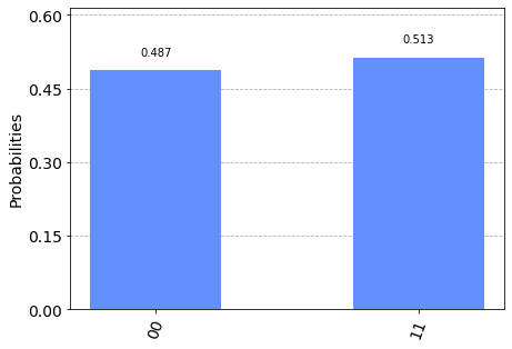
Total count for 00 and 11 are: {'00': 487, '11': 513}
     ┌───┐     ┌─┐
q_0: ┤ H ├──■──┤M├───
     └───┘┌─┴─┐└╥┘┌─┐
q_1: ─────┤ X ├─╫─┤M├
          └───┘ ║ └╥┘
c: 2/═══════════╩══╩═
                0  1
# Plot a histogram
plot_histogram(counts)

순차적 작업 흐름
위의 프로그램은 다음의 여섯 단계로 나누어 질 수 있다.
패키지 가져오기
변수 초기화하기
게이트 추가하기
회로 가시화하기
실험 시뮬레이션하기
결과 시각화하기
1단계: 패키지 가져오기
프로그램에 필요한 기본적인 요소들은 다음과 같이 가져올 수 있다:
import numpy as np
from qiskit import QuantumCircuit
from qiskit.providers.aer import QasmSimulator
from qiskit.visualization import plot_histogram
In more detail, the imports are
QuantumCircuit: can be thought as the instructions of the quantum system. It holds all your quantum operations.QasmSimulator: is the Aer high performance circuit simulator.plot_histogram: 히스토그램을 생성한다.
2단계: 변수 초기화하기
다음 코드의 줄을 보자
circuit = QuantumCircuit(2, 2)
Here, you are initializing with 2 qubits in the zero state; with 2
classical bits set to zero; and circuit is the quantum circuit.
구문:
QuantumCircuit(int, int)
3단계: 게이트 추가하기
게이트들을 (연산들을) 추가하여 회로의 레지스터들을 조작할 수 있다.
다음 세 줄의 코드를 참고하자:
circuit.h(0)
circuit.cx(0, 1)
circuit.measure([0,1], [0,1])
The gates are added to the circuit one-by-one to form the Bell state
위의 코드는 다음의 게이트들을 적용한다:
QuantumCircuit.h(0): A Hadamard gate \(H\) on qubit 0, which puts it into a superposition state.QuantumCircuit.cx(0, 1): A controlled-Not operation (\(CNOT\)) on control qubit 0 and target qubit 1, putting the qubits in an entangled state.QuantumCircuit.measure([0,1], [0,1]): if you pass the entire quantum and classical registers tomeasure, the ith qubit’s measurement result will be stored in the ith classical bit.
4단계: 회로 시각화하기
You can use qiskit.circuit.QuantumCircuit.draw() to view the circuit that you have designed
in the various forms used in many textbooks and research articles.
circuit.draw()
     ┌───┐     ┌─┐
q_0: ┤ H ├──■──┤M├───
     └───┘┌─┴─┐└╥┘┌─┐
q_1: ─────┤ X ├─╫─┤M├
          └───┘ ║ └╥┘
c: 2/═══════════╩══╩═
                0  1
In this circuit, the qubits are ordered with qubit zero at the top and qubit one at the bottom. The circuit is read left-to-right, meaning that gates which are applied earlier in the circuit show up farther to the left.
QuantumCircuit.draw() 나 qiskit.visualization.circuit_drawer() 에 사용되는 기본 백엔드는 텍스트 백엔드이다. 하지만 당신의 로컬 환경에 따라 필요에 맞는 좀 더 적절한 백엔드를 사용하고 싶을 수 있다. 이는 사용자 환경 파일을 통해 변경이 가능하다. 기본적으로 사용자 환경 파일은 ~/.qiskit/settings.conf 디렉토리에 저장되어야 하고 .ini 확장자를 가져야 한다.
예를 들어, Matplotlib 그리기 설정을 위한 settings.conf 파일은 다음과 같다:
[default]
circuit_drawer = mpl
You can use any of the valid circuit drawer backends as the value for this config, this includes text, mpl, latex, and latex_source.
5단계: 실험 시뮬레이션 하기
Qiskit Aer is a high performance simulator framework for quantum circuits. It provides several backends to achieve different simulation goals.
만약 Aer 설치에 문제가 있으면, 대신 Basic Aer를 사용할 수 있는데 이는 Aer`를 `BasicAer 로 대체함으로써 가능하다. Basic Aer는 Qiskit Terra에 포함되어 있다.
import numpy as np
from qiskit import QuantumCircuit, transpile
from qiskit.providers.basicaer import QasmSimulatorPy
...
To simulate this circuit, you will use the qasm_simulator. Each run of this
circuit will yield either the bit string 00 or 11.
simulator = QasmSimulator()
compiled_circuit = transpile(circuit, simulator)
job = simulator.run(compiled_circuit, shots=1000)
result = job.result()
counts = result.get_counts(circuit)
print("\nTotal count for 00 and 11 are:",counts)
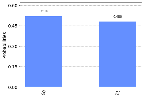
Total count for 00 and 11 are: {'00': 520, '11': 480}
As expected, the output bit string is 00 approximately 50 percent of the time.
The number of times the circuit is run can be specified via the shots
argument of the execute method. The number of shots of the simulation was
set to be 1000 (the default is 1024).
Once you have a result object, you can access the counts via the method
get_counts(circuit). This gives you the aggregate outcomes of the
experiment you ran.
6단계: 결과 시각화하기
Qiskit provides many visualizations,
including the function plot_histogram, to view your results.
plot_histogram(counts)

The observed probabilities \(Pr(00)\) and \(Pr(11)\) are computed by taking the respective counts and dividing by the total number of shots.
참고
Try changing the shots keyword in the execute method to see how
the estimated probabilities change.
다음 단계
이제 기본기를 익혔으므로, 다음 학습 자료들을 참고할 수 있다: